
Connect a Schneider energy meter to AWS IoT in 4 steps
Cloud monitoring Modbus RTU meters using the nodeG5 edge IIoT Gateway


-
Set up a Schneider iEM2150 Energy Meter as a Modbus RTU slave interfaced to a nodeG5 gateway Modbus master.
-
Support up to 32 Modbus devices, including meters and remote I/O terminal.
-
Connect to an AWS IoT Service via wired Ethernet, WIFI or cellular 4G.
Step 1: Hardware Wiring

Make the Serial RS-485 connection shown above using a 2 wire half duplex cable.
(Note maximum cable length depends on baudrate and cable quality, e.g. using 24AWG shielded twisted pair, about 100Kbit/sec at 1000m.)

Image courtesy of eng-tip.com
Step 2: Schneider Meter Configuration
Use the front display/button on the meter to set the serial parameters as below.
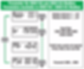
All slave devices connected on the RS-485 network must each have a unique address ranging from 1 to 247. Also make sure that the baudrate and parity for all slave devices and master must be the same.
Step 3: Connect Meter to Gateway
Using a configuration file (\user\iotasset.json) to map the required Modbus registers allows you to customise to a high degree the data read during each polling cycle. This also makes the nodeG5 compatible with other Modbus or CAN Bus devices from various manufacturers you may have in your set up.
We will take you through the steps to write your own iotasset.txt file. Note that we will be referencing the Modbus register table from your product user manual (see sample below):

And here is a sample of the iotasset.json.
{
"MODBUS":[
{
"Key":"M1_Current",
"IOTMODE":"1",
"MODBUSTYPE":"RTU",
"RTUPORT":"A",
"NODEID":"1",
"MODBUSFC":"3",
"REGADDR":"2999",
"NUMREGS":"2",
"DATATYPE":"FLOAT32ABCD",
"SCALEMUL":"0.1",
"SCALEADD":"0"
},
{
"Key":"M1_Voltage",
"IOTMODE":"1",
"MODBUSTYPE":"RTU",
"RTUPORT":"A",
"NODEID":"1",
"MODBUSFC":"3",
"REGADDR":"3027",
"NUMREGS":"2",
"DATATYPE":"FLOAT32ABCD"
},
{
"Key":"M1_ActivePower",
"IOTMODE":"1",
"MODBUSTYPE":"RTU",
"RTUPORT":"A",
"NODEID":"1",
"MODBUSFC":"3",
"REGADDR":"3053",
"NUMREGS":"2",
"DATATYPE":"FLOAT32ABCD"
}
]
}
We will now configure the gateway's serial port to operate as required for the attached Modbus devices. Go to the Port Settings tab and enter the following settings.

Then, go to the IOT Hardware menu to set the Hardware interface to "Modbus master" and register the polling configuration as required by the user (Note that all other interfaces like CAN bus and BLE can also run concurrently).

After these settings are updated, REBOOT the gateway. The user can then check the Modbus sensor data collected (JSON Data) or delete for testing.
In the top example, we are configuring to read Current (A) register frm meter Modbus address 1, register 3000 (Schneider mandates a -1 offset) and name data field name, as "M1_Current".
The gateway is also able to apply a customer multiplier (x0.1 in this case) and offset (0 in this case) to match the requirements of their cloud service.
Once you have configured your iotasset.txt file the new device configurations can be updated to your IoT gateway securely over the air. The gateway HTTPS connected web console must be accessible, either via local network (LAN or WLAN) or over a cellular network with an assigned public IP address
(If you do not have an Internet connection, you can follow the alternative steps here).
Log into your web console and go to the <IOT Hardware> tab, click on 'UPDATE FIRMWARE' in the Firmware Update section

In the new window, click on 'CHOOSE FILE' and select from your local folder the updated iotasset.txt file then click on 'UPLOAD FIRMWARE FILE'. After the upload is successful you will need to close the page and log in again for security purpose.
Step 4: Connecting to an AWS IoT Service
Now that the connectivity between the Schneider meter and the nodeG5 gateway has been set, we will then look at getting the data onto a designated cloud service. We support an open customer software and 3rd party API (e.g. REST API for HTTP, HTTPS and MQTT) integration to connect to a chosen cloud data or dashboard service (or to use for on board data processing).
Direct deployment on Azure, AWS IoT or Ubidots can also be done as these IoT clients have been integrated on the nodeG5 Gateway. For this project, we are going to showcase using AWS IoT
(note that an AWS account is required to continue this tutorial).
Creating a new AWS IoT Thing
First log into your AWS IoT Management Console and create a Thing:
AWS IoT > Manage > Thing > Create
Next go to:
Secure > Certificates
Then download the 'Certificate' & 'Private Key File'.
Ensure the Certificate is "Active", otherwise activate it under ACTIONS in
Things > Your Certificate > Security

Updating your IIoT Gateway
Create a new local folder and name it "AWS".
Save the downloaded certificate files into this folder and rename them as the following:
"certificate.pem.crt"
"private.pem.key"
Next zip the folder (ensure that you zip the entire folder and not just the files inside).
Then log into your nodeG5 web console and go to the <Management> tab.
Patch the zipped folder to the gateway using the UPDATE FIRMWARE button.
Creating a Security Policy for your Thing
In your AWS IoT Management Console go to:
Secure > Policies > Create

At <Things>, select your new Thing then click on
Security > Certificates > Policies
Under <Actions>, choose to Attach a Policy:

Configuring your nodeG5 IoT Gateway to send data to your AWS Account
Now, you are ready to configure your gateway to send AWS IoT endpoint to feed data to your AWS applications. In the nodeG5 web configuration menu, go to the <IoT Client> tab and configure your AWS client settings according as per your AWS end point and Thing settings. Then REBOOT your gateway.

Next go back to go your AWS IoT console and subscribe to the Topic to "Test" that data is being received.
