
How to send CAN Bus OBD2 equipment data onto a cloud platform or server using MQTT?

The diagnostic data from vehicles can be sent to a server or cloud for industrial intelligence applications with the use of IoT gateways that are equipped with the CAN OBD2 protocol & appropriate industrial certifications. The gateway organises the data collection and sends it using messaging protocols like MQTT.
Furthermore, devices like the nodeG5 gateway can also embed additional hardware or software to combine a range of complimentary functions on a single device.
-
Adding cellular & GPS modules enable heavy vehicles to be monitored on-the-move, together with positional tracking.
-
Integrated clients from major cloud platforms like Azure & AWS on the firmware helps the set-up for these applications be done faster & more reliably, reducing the engineering time needed for these projects.
-
FOG compute, edge processing or machine learning capabilities allow ground assets to spend less time communicating with the server or cloud, react more quickly to changes, and operate reliably even in extended offline periods.
The following tutorial gives a step-by-step example of connecting data from a CAN Bus OBD2 device (OZEN Elektronik OE91C1610 simulator) to a dashboard on AWS IoT Core.
Step 1: Wire up the CAN Bus OBD2 ECU to the Gateway.

OZEN Elektronik OE91C1610 (J1962 female OBD)
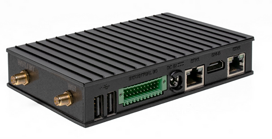
nodeG5 Gateway
We will start by connecting the devices together. You will need to refer to the respective user manuals for the pin out configuration of each device. The above diagram shows the signal connection from the OZEN board to the CAN Port E of the nodeG5 IoT gateway using a shielded twisted pair cable.
Step 2. Match the baud rates of both devices.
We need to match the baud rates on both devices. Use the DIP switch on the ECU board to select CAN frame ID 11-bit type. For the CAN BUS baud rate, select 250 000 bps.

Then log into the gateway's web configuration menu. Go to the <Port Settings> tab and enter the following settings below.

Once you are done click the 'UPDATE' button & REBOOT the gateway to save your settings.
Step 3: Map out the data parameters you want to collect.
Next, we will map out the individual sets of data that we want to collect from the ECU. Because different makers of CAN devices will utilise different Parameter ID (PID) settings, if we want to be brand agnostic for cost or product feature reasons, we need to find a universal way to detail the instructions to the gateway. On top of that, data formatting requirements are also different between each cloud platform. This adds to the need for a nimble approach.
Without engineering codes from scratch, a simple but flexible method is to map the parameters we want to monitor onto a configurable file known as an 'iotasset' that's read by the gateway. The example below shows how the "engine coolant temperature" parameter can be translated from the OZEN device user manual to our OBD2 iotasset.json format template.
We begin by obtaining the below PID info from the product's user manual.

When we will follow the OBD2 iotasset.json format template to configure the instructions for polling "engine coolant temperature" to the gateway on a simple program like notepad, we get the following results. I have also added samples for other data such as 'engine rpm' and 'vehicle speed' done using the same process.
{
"CANBUS":[
{
"Key":"OBD2EngineCoolantTemp", #Name data field name as "EngineCoolantTemp"
"IOTMODE":"1",
"CANBUSTYPE":"OBD2",
"CANPORT":"canE",
"CANIDREQUEST":"7DF", #"7DF" is the functional address of ECU based on !SO-15765-4 11 bit protocol
"CANIDRECEIVE":"7E8", #"7E8" is the response message ID used to filter the response message from the query
"CANMODEPID":"0105", #"0105" is the CAN request ECM mode 01 & PID 05
"BYTESTART":"4", #The response data is located at offset +3 from the first byte
"BYTECOUNT":"1", #The response data has a length of 1 byte
"DATATYPE":"UINT8",
"SCALEMUL":"1", #The gateway is able to apply a multiplier (x1 in this case) to match AWS requirements
"SCALEADD":"-40" #The gateway is able to apply an offset (-40 in this case) to match AWS requirements
},
{
"Key":"OBD2EngineRPM",
"IOTMODE":"1",
"CANBUSTYPE":"OBD2",
"CANPORT":"canE",
"CANIDREQUEST":"7DF",
"CANIDRECEIVE":"7E8",
"CANMODEPID":"010C",
"BYTESTART":"4",
"BYTECOUNT":"2",
"DATATYPE":"UINT16HL",
"SCALEMUL":"0.25",
"SCALEADD":"0"
},
{
"Key":"OBD2VehicleSpeed",
"IOTMODE":"1",
"CANBUSTYPE":"OBD2",
"CANPORT":"canE",
"CANIDREQUEST":"7DF",
"CANIDRECEIVE":"7E8",
"CANMODEPID":"010D",
"BYTESTART":"4",
"BYTECOUNT":"1",
"DATATYPE":"UINT8"
}
]
}
Now that you have configured your device configuration file, we can update it to your nodeG5 gateway securely over the air. The gateway HTTPS connected web console must be accessible, if you do not have an Internet connection, you can follow the alternative steps here).
Log into the nodeG5 (the default address is 192.168.1.1) and enter in the user name and password. Go to the <Management> tab in the web configuration menu. Enable the SSH option (see below) and click the 'UPDATE' button to save your settings. Then reboot the gateway.

Then log in again, go to the <IOT Hardware> menu to set the CAN bus mode to "Query mode" and register the polling configuration as required by the user. Click 'UPDATE' to save your settings.
(Note that all other interfaces like Modbus and BLE can also run concurrently).

Next, click “Upload iotasset.json” button and in the new window, use the 'CHOOSE FILE' tab to select the above prepared file from your local folder to to send over to nodeG5. The user can also confirm the status of iotasset.json file upload by clicking on Diagnostics::Check File.
After these settings are updated, REBOOT the gateway. The user can then check the CAN BUS vehicle data collected (Diagnostics::JSON Data) or delete for testing.
Step 4: Connect the collected data to your AWS IoT Cloud Service
Now that the connectivity between the ECU Simulator and the nodeG5 gateway has been set, we will then look at getting the data onto a designated cloud service. We support an open customer software and 3rd party API (e.g. REST API for HTTP, HTTPS and MQTT) integration to connect to a chosen cloud data or dashboard service (or to use for on board data processing).
Direct deployment on Azure, AWS IoT or Ubidots can also be done as these IoT clients have been integrated on the gateway. For this project, we are going to showcase using AWS IoT
(note that an AWS account is required to continue this tutorial).
1. Create a new AWS IoT Thing
First log into your AWS IoT Management Console and create a Thing:
AWS IoT > Manage > Thing > Create
Next go to:
Secure > Certificates
Then download the 'Certificate' & 'Private Key File'.
Ensure the Certificate is "Active", otherwise activate it under ACTIONS in
Things > Your Certificate > Security

2. Update your IIoT Gateway
Create a new local folder and name it "AWS".
Save the downloaded certificate files into this folder and rename them as the following:
"certificate.pem.crt"
"private.pem.key"
Next zip the folder (ensure that you zip the entire folder and not just the files inside).
Then log into your nodeG5 web console and go to the <Management> tab.
Patch the zipped folder to the gateway using the UPDATE FIRMWARE button.
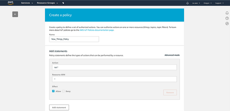
3. Create a Security Policy for your Thing
In your AWS IoT Management Console go to:
Secure > Policies > Create
At <Things>, select your new Thing then click on
Security > Certificates > Policies
Under <Actions>, choose to Attach a Policy:

4. Configure your nodeG5 IoT Gateway to send data to your AWS Account
Now, you are ready to configure your gateway to send AWS IoT endpoint to feed data to your AWS applications. In the web configuration menu, go to the <IoT Client> tab and configure your AWS client settings according as per your AWS end point and Thing settings. Then REBOOT your gateway.

Next go back to go your AWS IoT console and subscribe to the Topic to "Test" that data is being received.

Congratulations! You have succesfully sent your Modbus or CAN bus data to your AWS IoT endpoint and ready to, for example, push the data to a S3 bucket using a Rule in 'Act > Rules'.
The nodeG5 AWS IoT client side is built using AWS IoT Device SDK for Python and users are free to install, modify our device client codes for enhanced edge capabilities or other required functionalities.
See our guides below for connecting to other supported IoT platforms includes Azure IoT and Ubidots. Here is a sample dashboard from Ubidots.
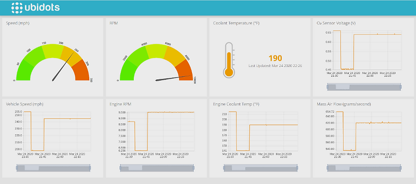
Guides to connect other Cloud Platforms


Connecting to Microsoft Azure IoT Hub
Connect to Ubidots IOT Platform